From the class Hypertools · Fall 2022
My friend is in a lighting design class and had an assignment in which he had to propose a speculative lighting design for a real place. As he has just moved into a new apartment, he decided to design lighting for his own room. His idea consisted of a CCT (Correlated Color Temperature) LED strip along the ceiling that would change its color temperature depending on the position of his murphy bed; Cool white when the bed is up and warm white when the bed is down. The idea behind this being that the cool lighting and extra space will make the room more conducive to productivity, while the warm lighting and bed down make the room more conducive to relaxing. He approached me about potentially helping him make his speculative design into a reality, just for fun, and I thought the pursuit of this idea would be a perfect potential arduino based I/O hardware interaction so I agreed.

The first prototype that I made was to learn how to use the ultrasonic sensor. The ultrasonic sensor was what I decided to use to define the current state of the murphy bed, up or down. I found that there was a hidden space under the murphy bed that is out of sight whether the bed is up or down. The space would fit the ultrasonic sensor and had a clear change in distance for the sensor to read and report when the bed changed states. The ultrasonic sensor also had more leeway for error handling. It does not require any precise positioning, physical switch actuation, or moving parts. If anything ever needs to be adjusted, it would only be the single number that defines threshold conditional in the code, and I really don’t see any reason that it would ever really need to be changed.
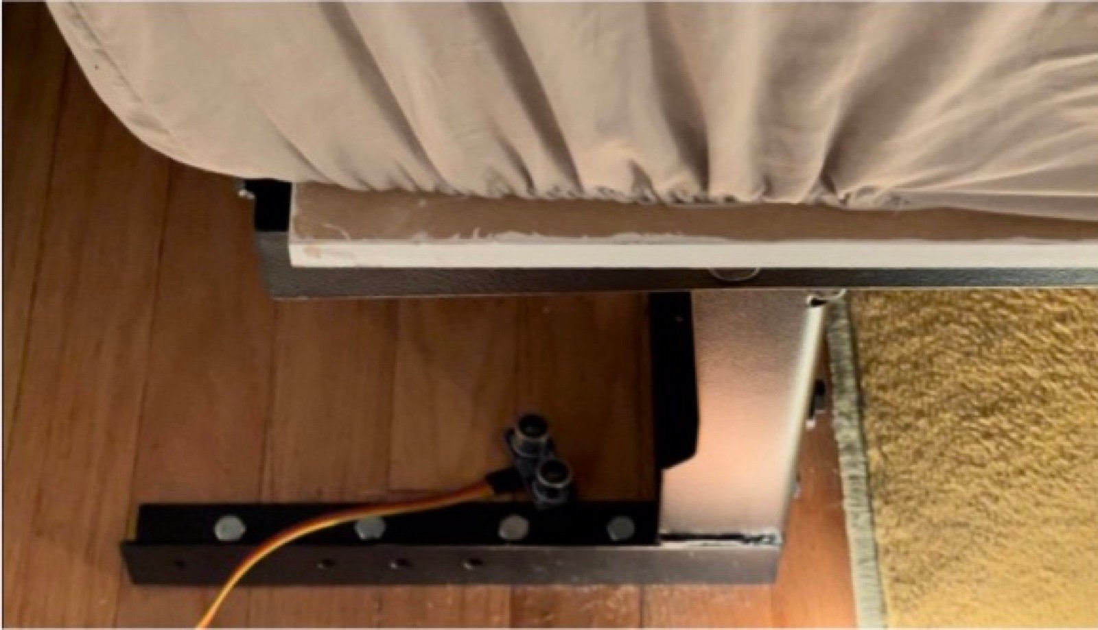
Ultrasonic sensor reading down position.
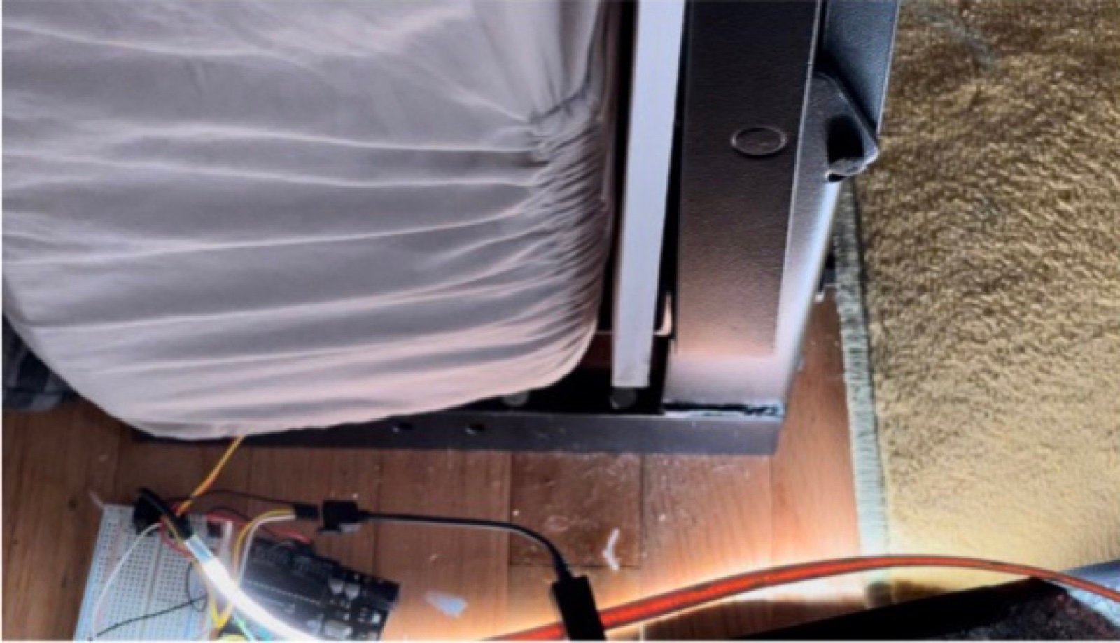
Ultrasonic sensor reading up position
Once I knew that the ultrasonic sensor would be how I defined the position of the bed in my hardware interaction I had to learn how to use it. To do this I made an initial prototype that was placed under the murphy bed in the proposed final position. The prototype was then programmed to send out a 10 microsecond pulse that would measure the distance between the sensor and the bed and report that distance every half-second. With this I was able to record the measured values for the up and down state of the murphy bed, those values being about ~8 cm and ~28 cm respectively. The threshold value that I set was 18 cm, therefore if the ultrasonic sensor read < 18 cm it would report the bed state as down and if it read > 18 cm it would report the bed state as up. Later to verify that it was outputting the proper result, and to see if the result could trigger another action, I hooked up an red LED and had the arduino light up the LED when the bed state was reported as down.

Thes second prototype that I made was to learn how to interface with the CCT LED strip. A CCT LED strip has three interfacing copper pads on it. One for 24 V power, one to control the warm LEDs and the one to control the cool LEDs. It took a lot of research on my end and several technical hurdles to jump over before I could figure out how to interface the LED strip with the arduino let alone reliably control them.
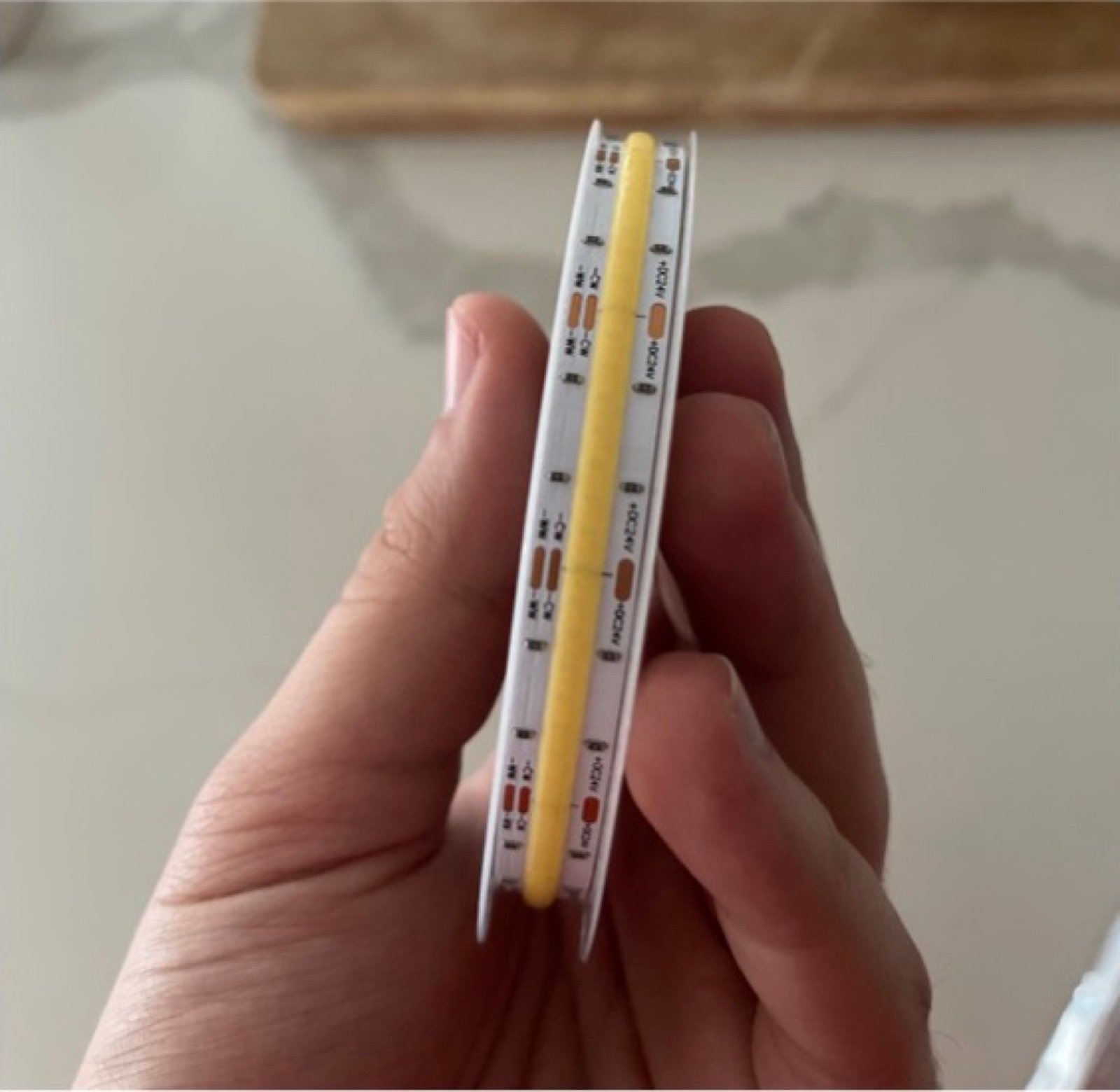
The first and biggest hurdle was that of using different voltages. The arduino runs on an input of 5 V via the usb port or 6-12 V via the input pins. The arduino can only output 5 V or 3.3 V via the output pins. The LED strip runs on 24 V power. My first technical deep dive was into learning all about voltage, current, resistance and power and how to properly use/discuss all of the above. I quickly discovered that I would need to find a creative solution to power both the arduino and LED strip off of the same AC outlet as the two devices require different DC voltages.
My first thought was to create a voltage divider that would step down the 24 V from the LED included power supply to 12 V using two resistors. I could then take that stepped down voltage and use it to power the arduino via input pins. I did not love this solution as it very quickly gave off more heat than I was comfortable with for a permanent solution, and in my research I came across the fact that for some reason or another 5 V via usb is the safest and most reliable way to power an arduino.
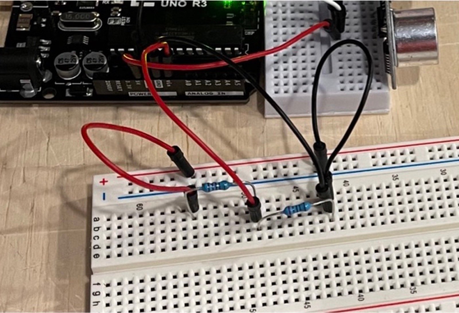
I also quickly learned that the power supply that came with the LEDs was under specced to provide sufficient power for the LED strip, let alone the arduino along with it. The provided power supply was 24 V / 1 A / 24 W. The LED strip itself draws 24 W of power and from my understanding, the power supply for any system should always be able to provide about 20% more power than is actually needed.
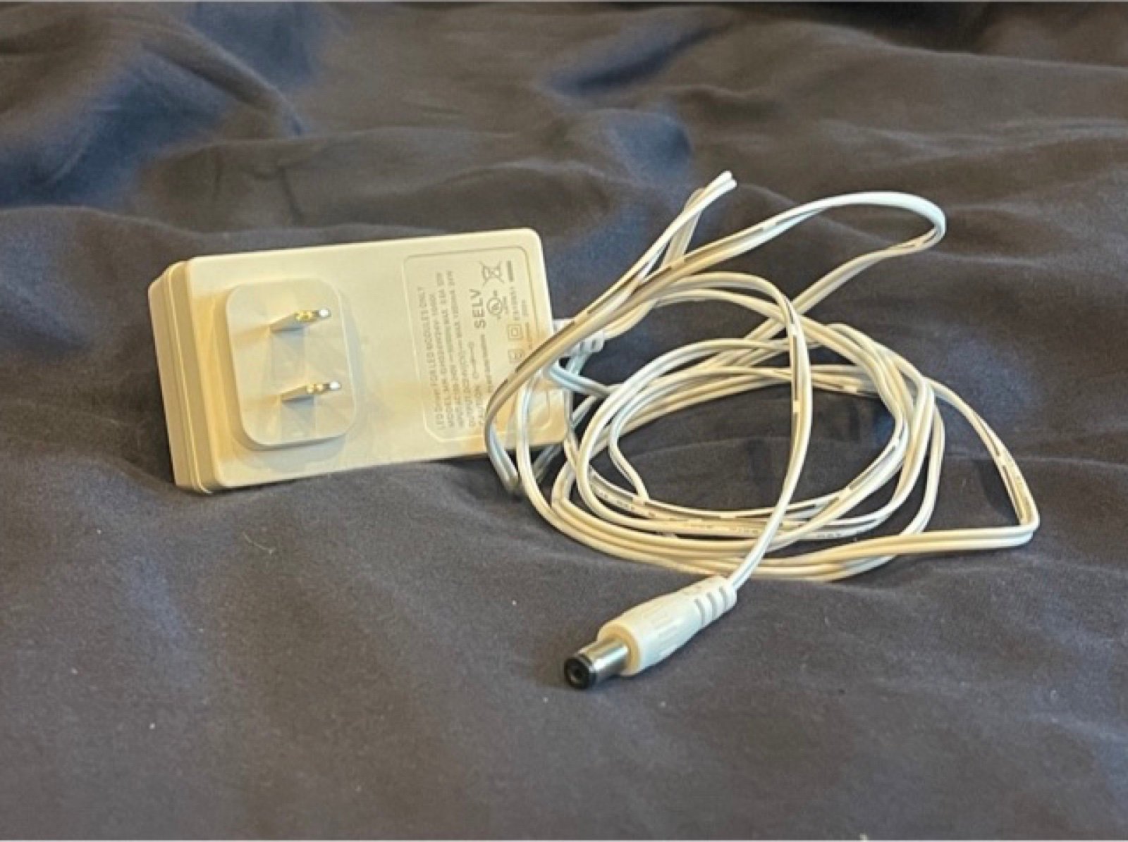
This meant I needed to find a new power supply. I eventually found and bought one that supported 24 V / 10 A / 240 W. This rating was able to sustain way more than my calculated needed power specs of 24 V / 1.175 A / 28.2 W, 20% overhead included, which means we could potentially add more load to it with future lighting if we wanted to.

I also found and ordered a DC - DC buck converter module that can take 12/24 V DC and output 5 V / 3 A through a USB port, perfect for wiring in and powering the arduino off of the new 24 V power supply. This meant everything could now be powered off of one outlet.

Once the arduino and LED strip could both be powered reliably, I could begin figuring out how to control said LED strip. I took a multimeter and began measuring different values across the LED strip while it was being controlled and powered with its own out of the box controller, remote, and power supply. This revealed to me that the lines that controlled the cool and warm LEDs respectively were simply adjusting voltage between 0-24 V which respectively corresponded to off and full brightness. The issue now in controlling those data lines was that, like previously stated, the arduino can only output 3.3 or 5 V, and with not nearly enough amperage to properly control the LEDs. In researching a solution to this I came across logic level metal oxide semiconductor field effect transistors or MOSFETs. The MOSETs function as a form of voltage regulator, allowing to pass large power through from the 24 V power supply but to control that power via the output pins of the arduino.
With these MOSFETs and new power supply I was in theory able to control the lights properly. To create a prototype that controlled the lights I coded a short program that would, upon reset of the arduino, over 2.5 seconds ramp up the warm LEDs from zero to full brightness and then over the next 2.5 seconds do the same with the cool LEDs. It would then maintain full brightness with both cool and warm LEDs for 5 seconds before ramping down the brightness of both color temperatures at the same time back to zero over the next 2.5 seconds. The whole interaction from start to finish takes 12.5 seconds and illustrates that the 2 color temperatures can display at any brightness, can increase or decrease in brightness, and can do so independently or together. This prototype did not make use of the ultrasonic sensor as a conditional however, it simply ran a function upon booting or resetting, nonetheless it serves the function that I needed it to; The LED strip can be controlled by the arduino.
In the end, the final implementation was pretty simple. It was only a matter of combining the physical and digital components of both prototypes. Taking the conditional and ultrasonic sensor from the first prototype and building it into the controlled LEDs of the second prototype. The final object is yet to be installed as there are some last minute upgrades and changes that I would like to implement beforehand.
Some of these changes include but are not limited to:
After these final touches have been applied we will happily install the system permanently. Below are some images of the final object in use with color temperatures at their respective extremes for sake of easy visual distinction within this documentation.
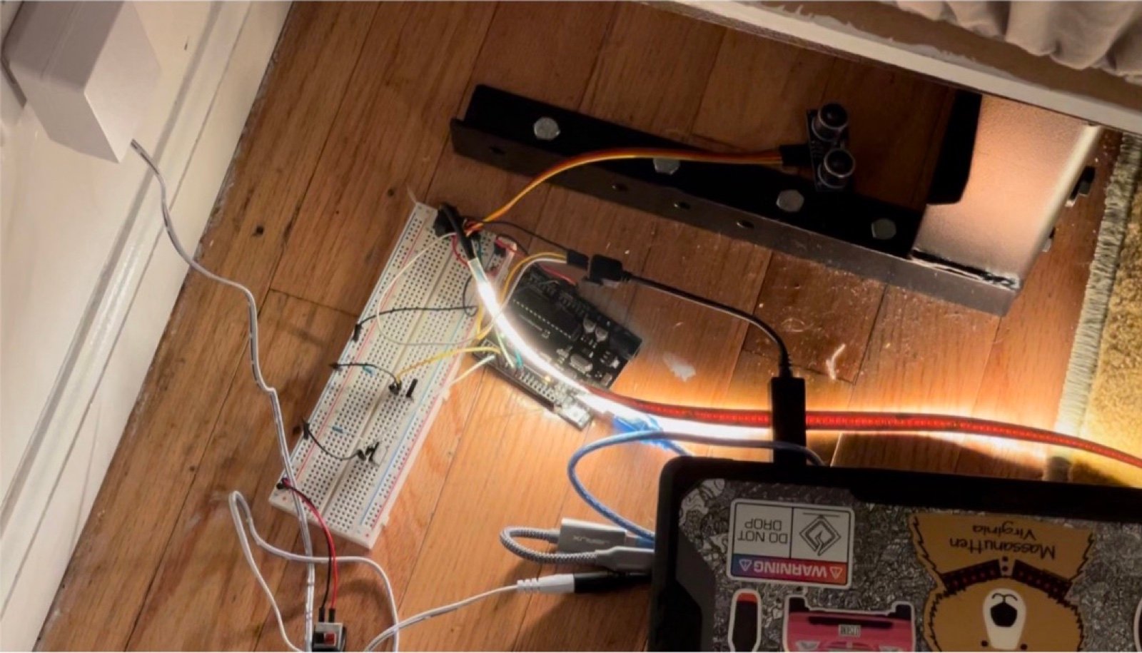
Final (but in actuality, semi-final) Implementation.
1 - UltrasonicTest/1 - UltrasonicTest.ino
/*
 * Wiring: Ultrasonic Sensor -> Arduino:
 * - VCC  -> 5VDC
 * - TRIG -> Pin 9
 * - ECHO -> Pin 8
 * - GND  -> GND
 */

int trigPin = 9;  // TRIG pin
int echoPin = 8;  // ECHO pin
int ledPin = 10;  // led pid

float duration_us, distance_cm;

void setup() {
  // begin serial port
  Serial.begin(9600);

  // configure the trigger pin to output mode
  pinMode(trigPin, OUTPUT);
  // configure the echo pin to input mode
  pinMode(echoPin, INPUT);
  // configure built in LED
  pinMode(ledPin, OUTPUT);
}

void loop() {
  // generate 10-microsecond pulse to TRIG pin
  digitalWrite(trigPin, HIGH);
  delayMicroseconds(500);
  digitalWrite(trigPin, LOW);

  // measure duration of pulse from ECHO pin
  duration_us = pulseIn(echoPin, HIGH);

  // calculate the distance
  distance_cm = 0.017 * duration_us;

  // print the value to Serial Monitor
  Serial.print("distance: ");
  Serial.print(distance_cm);
  Serial.println(" cm");

  delay(500);
}
2 - LEDStripTest/2 - LEDStripTest.ino
//define pins for the red, green and blue LEDs
#define wLedPin 6
#define cLedPin 5

//overall brightness value
int brightness = 255;
//individual brightness values for the red, green and blue LEDs
int wBright = 0;
int cBright = 0;

int fadeSpeed = 10;


void setup() {
  //set up pins to output.
  pinMode(wLedPin, OUTPUT);
  pinMode(cLedPin, OUTPUT);
}

void TurnOn() {

  for (int i = 0; i < 256; i++) {

    analogWrite(wLedPin, wBright);
    wBright += 1;
    delay(fadeSpeed);
  }

  for (int i = 0; i < 256; i++) {

    analogWrite(cLedPin, cBright);
    cBright += 1;
    delay(fadeSpeed);
  }
}

void TurnOff() {
  for (int i = 0; i < 256; i++) {
    analogWrite(wLedPin, brightness);
    analogWrite(cLedPin, brightness);
    brightness -= 1;
    delay(fadeSpeed);
  }
}

void loop() {
  //Call the TurnOn method, wait, then call TurnOff
  TurnOn();
  delay(5000);
  TurnOff();
}
3 - Penultimate/3 - Penultimate.ino
//define pins
int usTrigPin = 9;
int usEchoPin = 8;
int warmLed = 6;
int coolLed = 5;

//define individual brightness values for the warm and cool LEDs
int wBright = 255;
int cBright = 0;

//define fade speed
int fadeSpeed = 10;

//define bed state
int bedState = 0;

int duration_us = 0;
int distance_cm = 0;


void setup() {

  // begin serial port
  Serial.begin(9600);

  //set up pins to output or input
  pinMode(usTrigPin, OUTPUT);
  pinMode(usEchoPin, INPUT);
  pinMode(warmLed, OUTPUT);
  pinMode(coolLed, OUTPUT);
}

void loop() {
  delay(500);
  UltraSonic();

  if (bedState = 0) {
    BedGoesUp();
  } else if (bedState = 1) {
    BedGoesDown();
  }
}

void UltraSonic() {
  // generate 10-microsecond pulse to TRIG pin
  digitalWrite(usTrigPin, HIGH);
  delayMicroseconds(500);
  digitalWrite(usTrigPin, LOW);

  // measure duration of pulse from ECHO pin
  duration_us = pulseIn(usEchoPin, HIGH);

  // calculate the distance
  distance_cm = 0.017 * duration_us;

  // print the value to Serial Monitor
  // Serial.print("distance: ");
  // Serial.print(distance_cm);
  // Serial.println(" cm");

  delay(500);

  if (distance_cm > 20) {
    bedState = 0;
  } else if (distance_cm < 20) {
    bedState = 1;
  }
}

void BedGoesUp() {
  for (int i = 0; i < 256; i++) {

    analogWrite(warmLed, wBright);
    wBright -= 1;
    delay(fadeSpeed);
  }

  for (int i = 0; i < 256; i++) {

    analogWrite(coolLed, cBright);
    cBright += 1;
    delay(fadeSpeed);
  }
}

void BedGoesDown() {
  for (int i = 0; i < 256; i++) {

    analogWrite(warmLed, wBright);
    wBright += 1;
    delay(fadeSpeed);
  }

  for (int i = 0; i < 256; i++) {

    analogWrite(coolLed, cBright);
    cBright -= 1;
    delay(fadeSpeed);
  }
}
4 - Final/4 - Final.ino
/*
 * Wiring: Ultrasonic Sensor -> Arduino:
 * - VCC -------> 5VDC
 * - TRIG ------> Pin 9
 * - ECHO ------> Pin 8
 * - GND -------> GND
 *
 * Wiring: CCT LED Strip -> Arduino:
 * - Warm LEDs -> Pin 6
 * - Cool LEDs -> Pin 5
 * - GND -------> GND
 */

int trigPin = 9;  // TRIG pin
int echoPin = 8;  // ECHO pin
int wLedPin = 6;  // ECHO pin
int cLedPin = 5;  // ECHO pin

float duration_us = 0;   // Ultra-sonic sensor output
float distance_cm = 0;   // Ultra-sonic sensor output converted to cm
float distance_x = 0;    // Last measured distance in cm
float distance_y = 0;    // Second to last measured distance in cm
float distance_z = 0;    // Third to last measured distance in cm
float distance_avg = 0;  // The Average of the last three measured distances in cm

int warmBrightness = 0;  // Initial brightness value for all warm LEDs
int coolBrightness = 0;  // Initial brightness value for all cool LEDs

int fadeSpeed = 10;  //Delay in milliseconds between each brightness incrementation

void setup() {
  // begin serial port
  Serial.begin(9600);

  // configure the trigger pin to output mode
  pinMode(trigPin, OUTPUT);
  // configure the echo pin to input mode
  pinMode(echoPin, INPUT);
  // configure the warm LED pin to output mode
  pinMode(wLedPin, OUTPUT);
  // configure the cool LED pin to output mode
  pinMode(cLedPin, OUTPUT);
}
void loop() {
  ultraSonic();
}

void ultraSonic() {
  // generate 10-microsecond pulse to TRIG pin
  digitalWrite(trigPin, HIGH);
  delayMicroseconds(10);
  digitalWrite(trigPin, LOW);

  // measure duration of pulse from ECHO pin
  duration_us = pulseIn(echoPin, HIGH);

  // calculate the distance
  distance_cm = 0.017 * duration_us;
  distance_z = distance_y;
  distance_y = distance_x;
  distance_x = distance_cm;
  distance_avg = ((distance_x + distance_y + distance_z) / 3);

  // if the bed is up
  if (distance_avg <= 11) {
    Serial.print("Bed is up. ");
    // if the lights are already cool
    if (coolBrightness == 255) {
      Serial.print("Lights are already cool. ");
      // print the value to Serial Monitor
      Serial.print("Avg Distance: ");
      Serial.print(distance_avg);
      Serial.println(" cm");
      delay(1000);
    }
    //if the lights are not already cool
    else {
      Serial.println("Raising color Temperature. ");
      for (int i = 0; i < 255; i++) {
        // turn off the warm LEDs
        analogWrite(wLedPin, warmBrightness);
        warmBrightness -= 1;

        // turn on the cool LEDs
        analogWrite(cLedPin, coolBrightness);
        coolBrightness += 1;

        delay(fadeSpeed);
      }
    }
  }
  // if the bed is down
  else {
    Serial.print("Bed is down. ");
    // if the lights are already warm
    if (warmBrightness == 255) {
      Serial.print("Lights are already warm. ");
      // print the value to Serial Monitor
      Serial.print("Avg Distance: ");
      Serial.print(distance_avg);
      Serial.println(" cm");
      delay(1000);
    }
    //if the lights are not already warm
    else {
      Serial.println("Lowering Color Temperature.");
      for (int i = 0; i < 255; i++) {
        // turn on the warm LEDs
        analogWrite(wLedPin, warmBrightness);
        warmBrightness += 1;

        // turn off the cool LEDs
        analogWrite(cLedPin, coolBrightness);
        coolBrightness -= 1;

        delay(fadeSpeed);
      }
    }
  }

}